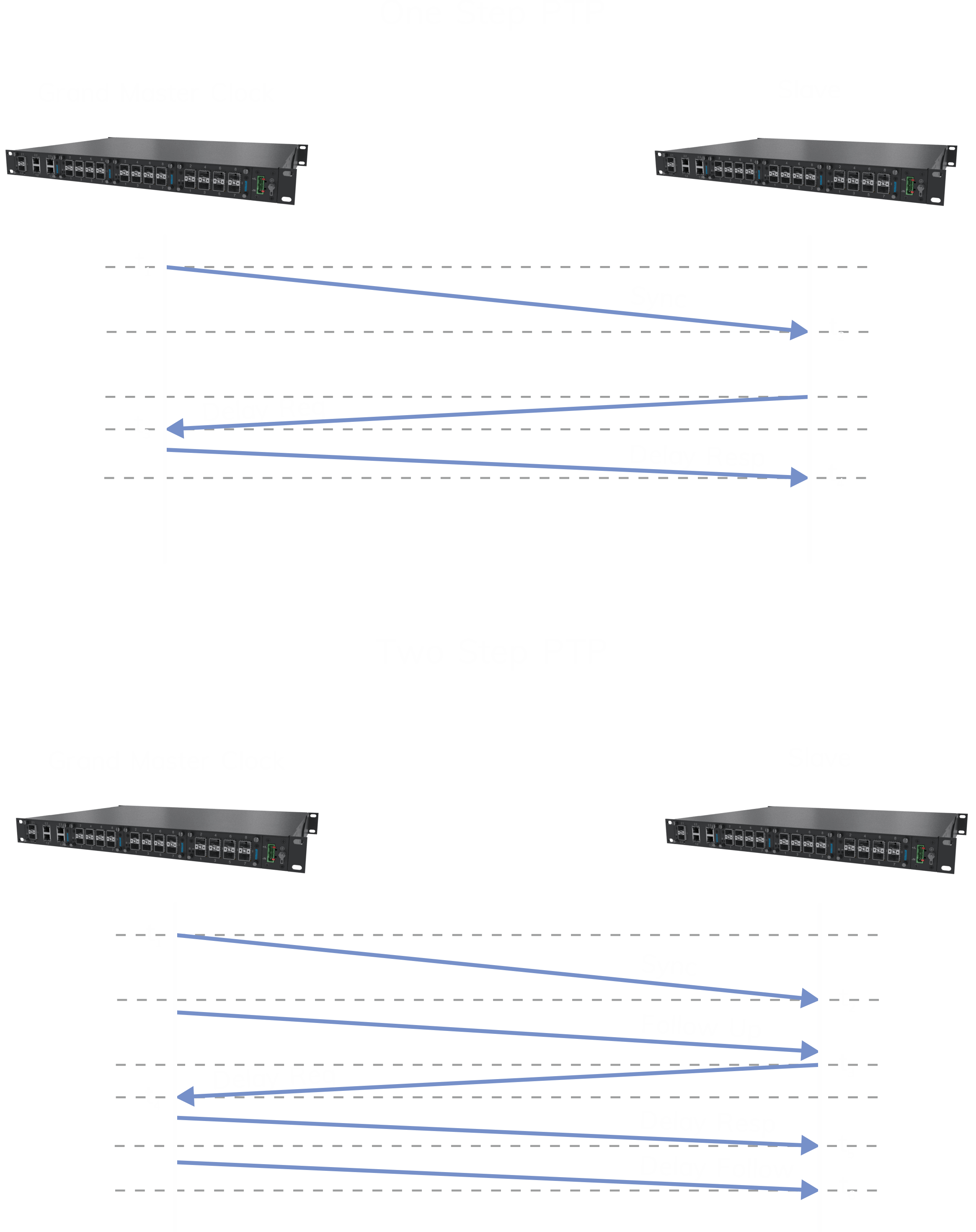
What is it?

The IEEE 1588-2008 standard defines the second generation of PTP, also known as PTPv2 or 1588v2. The PTP standard gives the possibility to obtain a very accurate time synchronization with Ethernet devices, by registering the exact time of receiving a PTP synchronization message. This information can compensate for the uncertainty introduced by real-time operating systems and other delays caused by the synchronization process in the main device as well as in the devices being synchronized.

The great advantage of PTPv2 is that it does not affect the operation of other protocols operating in the Ethernet network, so it can coexist on a single port with for 61850, 61850-8-1 GOOSE, DNP3, Sampled Values (SV) and other station automation protocols. Important during the construction of the station is to equip Ethernet switches with native PTP support, available only in the highest class of switches.

The key terms for learning about PTP

Timer white

Grandmaster clock

The main source of time in the PTP network, a clock which is usually equipped with a GPS/GLONASS/GALILEO receiver, the signal gained is used and distributed throughout the network.

Timer white

Master clock


It is a network clock behind the grandmaster, distributing the clock to other devices, while accepting a network load so as not to overload the grandmaster.

Timer white

Slave clock


Usually it is an end device, a receiver of
a time source with PTP, e.g. a safety relay at a power station.
It can also be
a device changing time from PTP to one of the older signals such as 1-PPS, IRIG-B or NTP time.

Timer white

Transparent clock

Ethernet switch, which is used to measure the time needed to transmit the PTP synchronization from the master block to the end device (Slave clock) and transmit this information to the receiving clocks to devices working on both sides.

Timer white

Boundary clock

Is a secondary clock for the Master Clock, a multi-port time source for the transparent clock slaves.

Flexibility of PTP

PTP supports multiple master clocks, which choose between themselves one clock marked „grandmaster”. If the quality of the clock selected as master is reduced in real time it is possible to autonomously select a clock that will function as a new „grandmaster” with better accuracy than the current one.

One of the main features of PTP is its flexibility and can be used for many time synchronization applications with an accuracy of less than 10 ns.

Such accuracy could be achieved by adding a special profile stump for the Ethernet switch in PTPv2. Transparent Clock (TC) significantly simplifies the design of the network, thanks to the use of a transparent clock, PTP traffic in the network does not have to be given priority.

Transparent Clock measures the delay time between devices, which depends on the network load, nodal elements and track length between devices. This compensates for the delay and significantly improves the performance of the PTP network coexisting with other network traffic.

Two step and One step

In PTP, the most important issue is to determine the exact time at which the PTP Sync message is transmitted, which is received by the Ethernet interfaces of the slave clocks. It is not possible to determine the time of sending the message until it is sent. The time is marked in the Ethernet interface that supports PTP, then makes this information available to the grandmaster. The next step is to send a Follow Up message, which transfers this exact time to the nearest device and terminal. The slave clocks add their estimated delay to the Follow Up message for maximum accuracy. The combination of Sync and Follow Up messages is called „Two Steps”.

By using more advanced Ethernet switches it is possible to modify PTPv2 messages in real time, updating the exact timestamp during transmission. This avoids the need to send Follow UP messages and is called One Step. The Grandmaster sends the timestamp in the Sync message, and the transparent clocks provide an estimate of the network delay in correcting the Sync message, not in the Follow Up message. This significantly reduces network traffic.

System architecture with precise PTPv2 synchronization can build using One step and Two step in one network. The switches will then have to take into account the information about the updates that have been made to the Sync transparent one-step clocks messages and the updated information sent in the Follow Up transparent two-step clocks messages.

Power Profile

In the PTPv2 standard, profiles have been introduced, which allow for a number of options in terms of their configuration. The profiles define certain functions, identifying their specific application.

For the power industry, the IEEE Std C37.238-2011/2017 profile has been developed which, thanks to its optimized parameters and minimal user-side configuration, achieves synchronization accuracy of less than 1 µs with network topologies typical for substation automation systems.

The Management Information Base (MIB) for Simple Network Management Protocol (SNMP) is also defined in the Power Profile, which allows key device parameters to be monitored using standard network management tools. The performance of the time synchronization system is monitored in real time, and alerts are reported to the administrator in case of problems or anomalies.

Power Profile defines the requirements for Ethernet switches that can introduce an inaccuracy of no more than 50ns. According to the standard, the inaccuracy for Power Profile must not exceed 1 µs, hence the restriction to 16 Ethernet switches in the ring topology. The inaccuracy must also take into account the delay brought by the clock with GPS up to 200 ns according to the standard.

The profile requires that all PTPv2 messages on the Ethernet network should use peer to peer switches and all messages sent using Ethernet layer 2 frames. Peer to peer means that each PTP device exchanges messages with the adjacent device on the network to measure the path delay between them, thus avoiding communication with each slave. The total network latency is calculated by summing up the path latency and the time of the switch between the grandmaster clock and each slave clock. This has two advantages:

The movement and load that is directed to the main clock on the network does not suspend with the addition of other devices. Grandmaster only communicates with the Ethernet switch it is connected to.

The PTP system automatically compensates itself when a network connection fails and an alternative path is used. Path delays are measured on all network connections, even those that are blocked for normal traffic by SpanningTree protocols.

PTP Messages

Four classes for time synchronization have been defined for message transmission using Power Profile

A Fallow Up message that contains the precise timing of the previous Sync message by adding a delay information. The delay is the sum of the clock delay times resulting from the distance travelled and the propagation delays resulting from the slave clock.

Sync Messages which contains information about the main clock time in the form of the number of nanoseconds, seconds from midnight on 1 January 1970.

Peer Delay messages that are exchanged between adjacent devices to determine the latency of each of the paths between devices.

Announce messages are information messages sent by the grandmaster that contain details of time accuracy, e.g. from a GPS receiver, and other PTPv2 protocol information.

PTP benefits

PTP provides the possibility to use redundant grandmaster clocks with automatic emergency switching if the active grandmaster loses network connectivity or the clock quality deteriorates.

Any changes in summer time operation dates must only be made to the grandmaster and not to every device on the network. The mechanism used is defined in IEEE standard C37.238-2011/2017.

Propagation delays due to long cable paths are automatically compensated and tuning of connection and phaser measurement units in the field need not be done manually.

There are no configuration problems with UTC time or local time. A single time reference is used, so all Power Profile devices use the international atomic time TAI to avoid, among other things, summer time problems.

Power Profile transmits the local time offset, so there is no need to configure the local time zone on security relays.

In PTP, the message sending speed has been optimized to meet latency requirements below 1 µs and does not cause excessive traffic in a shared network.

The network can be expanded without unnecessary load on the grandmaster.

Both fiber optic and Ethernet twisted pair can be used for PTPv2 transmission.

Ethernet traffic does not affect the synchronization accuracy, only in case of network overload PTP messages will be lost. This situation can be avoided by using ethernet switches equipped with 10Gbit/s interfaces in the architecture. Thanks to that we save financial budget, the network with precise synchronization can be used for data transmission from synchrophasors to data transmission from IEC 61850 Processed Bus (MMS, GOOSE).

To increase the reliability of network connections between PTP devices, protocols allowing redundant Ethernet connections, such as RSTP, parallel PRP redundancy and HSR lossless ring can be used.